

The 7 Most Common Mistakes When Installing LED Strips

Team Factorled
2026-05-19 07:15:12
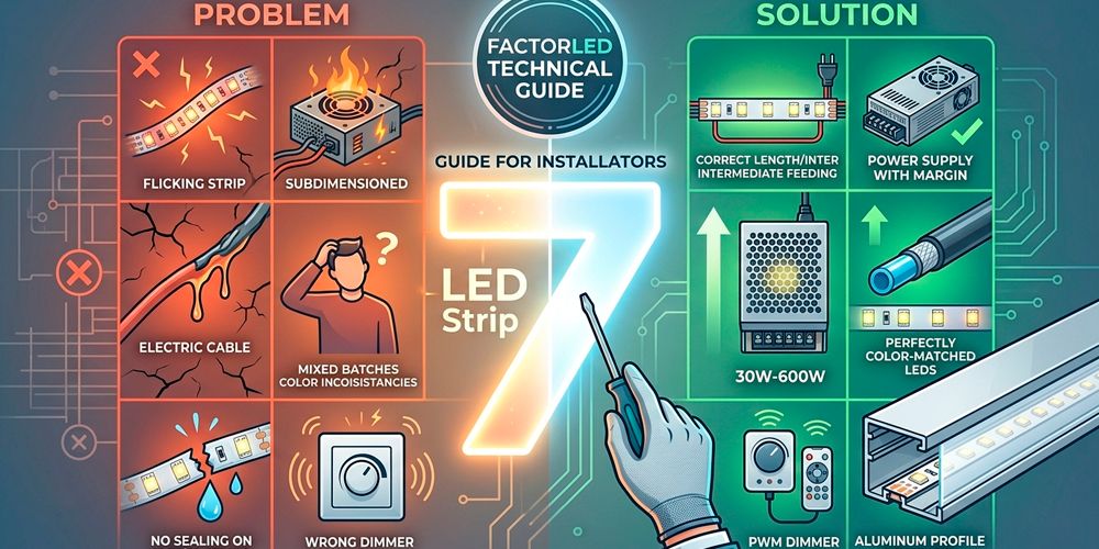
The 7 Most Common LED Strip Installation Mistakes
and how to avoid them costing you the entire project budget
LED strip lights are one of the most versatile and sought-after products on the market. They are also, alongside power supplies, the products that generate the most post-installation complaints when fitted incorrectly. The vast majority of failures are not product defects — they are sizing, installation or compatibility errors that recur systematically on job after job. This guide brings together the 7 most common mistakes from our technical support practice, with the precise fix for each one.
📌 Summary: the 7 mistakes at a glance
| # | Mistake | Consequence | Quick fix |
|---|---|---|---|
| 1 | Exceeding maximum run length without mid-point injection | Visible brightness drop from start to end of run | Feed from centre or add 2nd power supply |
| 2 | Undersizing the power supply | Overheating, flickering, premature failure | Total watts × 1.25 safety margin |
| 3 | Using cable with insufficient cross-section | Additional voltage drop, cable heat, fire risk | Min. 1.5 mm² standard; 2.5 mm² high power |
| 4 | Mixing different batches on visible runs | Perceptible colour temperature variation | Order entire run from the same batch |
| 5 | Installing without an aluminium heatsink channel | Overheating, lumen depreciation, short service life | Always use a channel with diffuser on fixed installs |
| 6 | Not sealing cut ends on IP67/IP68 strips | IP rating voided, short circuit from moisture ingress | Seal immediately with silicone or epoxy resin |
| 7 | Using an incompatible dimmer with low-voltage LED strip | Flickering, buzzing, premature driver failure | PWM dimmer rated for DC low voltage only |
The 7 mistakes in detail
Exceeding the maximum run length without mid-point power injection
🔍 Symptom
The far end of the strip is noticeably dimmer than the feed end. The client complains that the "lights aren't even".
⚙️ Root cause
Voltage drop along the strip reduces the voltage reaching the LEDs at the far end. On 12 V this becomes perceptible from around 4–5 m. On 24 V the threshold rises to 8–10 m.
⚠️ Consequence
Visually defective installation. Likely product return or remedial work at the installer's cost.
✅ Fix
- For 12 V strips: inject power every 4–5 m maximum. On longer runs, feed from the centre or add a second supply at the far end.
- For 24 V strips: limit of 8–10 m before additional injection.
- Professional option: use a parallel feed cable (power bus) that injects current at regular intervals — ideal for shop lineals and long continuous runs.
- With high-density strips (14–24 W/m): reduce these limits by 30–40%.
Undersizing the power supply
🔍 Symptom
The power supply runs very hot, the LEDs flicker under full load, or the unit shuts down on thermal protection after a few minutes of operation.
⚙️ Root cause
The supply is running at 100% of its capacity continuously. Power electronics components are not designed for sustained operation at their maximum rating — service life collapses.
⚠️ Consequence
Premature power supply failure (within weeks or a few months). Potential damage to the LED strips from voltage spikes at the point of failure. Client complaint.
✅ Fix
- Never run a power supply above 80% of its rated output in continuous use.
- Correct formula: Power supply wattage = (W/m × total metres) × 1.25
- If the result falls between two catalogue ratings, always select the higher one.
- When running multiple strips in parallel, sum all wattages before applying the 1.25 factor.
Reference table: correct power supply by strip configuration
| Strip configuration | Actual draw | Minimum supply | Recommended supply | Note |
|---|---|---|---|---|
| Strip 4.8 W/m × 5 m | 24 W | 30 W | 30 W or 45 W | 25% headroom |
| Strip 9.6 W/m × 5 m | 48 W | 60 W | 60 W or 75 W | 25% headroom |
| Strip 14.4 W/m × 5 m | 72 W | 90 W | 100 W | 38% headroom |
| Strip 9.6 W/m × 10 m | 96 W | 120 W | 120 W or 150 W | 25% headroom |
| Strip 14.4 W/m × 8 m | 115 W | 144 W | 150 W or 200 W | 30–74% headroom |
| Strip 24 W/m × 5 m | 120 W | 150 W | 150 W or 200 W | 25–67% headroom |
Using feed cable with insufficient conductor cross-section
🔍 Symptom
The strip works fine initially but brightness differences develop over time, the cable becomes warm to the touch, or in severe cases the cable insulation begins to melt.
⚙️ Root cause
An undersized cable introduces additional voltage drop before the strip and generates heat through the Joule effect. The higher the wattage and the longer the run, the more severe the problem.
⚠️ Consequence
Real fire risk in extreme cases. Installation non-compliant with BS 7671 (IET Wiring Regulations, 18th Edition). Accelerated strip degradation from undervoltage.
✅ Fix
- This refers to the cable between the power supply and the strip connection point — not the inter-section wiring within the strip run itself.
- The longer the cable run and the higher the wattage, the larger the conductor cross-section must be.
- In practice: minimum 1.5 mm² for the majority of standard domestic and commercial installations.
BS 7671 Warning
BS 7671 — the IET Wiring Regulations (18th Edition) — specifies minimum conductor cross-sections based on the maximum permissible current. In professional installations, cable sizing is not optional: it is a statutory requirement. An installation with undersized cable will not pass an NICEIC or NAPIT inspection, and failure to comply may void building insurance.
Recommended cable cross-sections by run length and wattage
| Distance supply→strip | Max. wattage | Cable cross-section | Notes |
|---|---|---|---|
| Up to 3 m | Up to 50 W | 0.75 mm² | Acceptable only for very short runs at low wattage |
| Up to 5 m | Up to 100 W | 1.5 mm² | Standard recommendation for the majority of installations |
| Up to 8 m | Up to 200 W | 2.5 mm² | Required for high-wattage strips (14–24 W/m) |
| Up to 15 m | Up to 300 W | 4 mm² | Medium-length runs with a centralised power supply |
| Up to 25 m | Up to 500 W | 6 mm² | Large installations; consider distributed power injection |
Mixing different production batches on visible adjacent runs
🔍 Symptom
Two seemingly identical sections (same model, same part number) placed side by side show a noticeable difference in colour tint. The client reports that the "lights don't all match".
⚙️ Root cause
Colour temperature and luminous flux vary slightly between production batches. A difference of 3 MacAdam steps or more is visible to the naked eye in continuous lighting runs.
⚠️ Consequence
Aesthetic complaint requiring full replacement of the installation with material from a single matching batch. Materials and labour costs fall to the installer.
✅ Fix
- Before confirming an order for lineals or continuous lighting, check with Factorled that the entire required meterage is available from the same batch.
- Always order 10–15% additional material from the same batch for future repairs.
- If batch consistency cannot be guaranteed, position batch changes at corners or physical breaks in the run where direct visual comparison is not possible.
- On large projects (>50 m of strip): request samples from the available batch before confirming the order.
Installing LED strip without an aluminium heatsink channel
🔍 Symptom
Strip fitted directly to timber, plasterboard or plastic gradually loses brightness over the first few months. By 12–18 months, lumen depreciation is clearly visible.
⚙️ Root cause
Without adequate heat dissipation, the LED chip junction temperature exceeds its optimal limit (85 °C), accelerating phosphor degradation and reducing luminous flux. This is the single biggest factor in premature LED strip ageing.
⚠️ Consequence
Loss of up to 30–40% of luminous flux within the first year. Actual service life of 10,000–15,000 hours instead of the warranted 50,000 hours. The client feels the product "wasn't up to scratch".
✅ Fix
- An aluminium channel reduces the strip operating temperature by 15–30 °C compared with direct mounting on an insulating surface.
- Strips up to 9.6 W/m: standard 15×7 mm profile is adequate.
- Strips at 14.4 W/m or above: profile with greater thermal mass (20×10 mm or larger).
- A polycarbonate diffuser softens the point-source line and delivers a professional finish that clients perceive as a mark of quality.
- Exception: temporary installations or exhibition displays. For all permanent work, always use a channel.
Not sealing cut ends on IP67/IP68 strips
🔍 Symptom
An IP67 strip installed externally or in a wet area fails by short circuit within a few months. On inspection, oxidation and moisture ingress are evident inside the strip.
⚙️ Root cause
IP67/IP68 strips only maintain their ingress protection rating when intact. Cutting the strip to length leaves the end open. Moisture penetrates by capillary action between the silicone sleeve and the PCB, causing contact oxidation and short circuit.
⚠️ Consequence
Complete installation failure. Short circuit that may also damage the power supply. In wet areas, energised water presents a genuine electrical safety hazard.
✅ Fix
- Immediately after cutting, apply neutral silicone or two-part epoxy resin to the cut end.
- Professional option: use dedicated end caps sized to the strip width (8, 10 or 12 mm).
- Allow to cure fully before exposing to moisture: minimum 24 hours for silicone, 4–6 hours for fast-cure epoxy.
- Also inspect the cable entry point — it is the second most vulnerable point in any waterproof installation.
Using an incompatible dimmer with low-voltage LED strip
🔍 Symptom
The LED strip flickers at low light levels, produces an audible buzzing, fails to dim at all (runs at 100% constantly), or the LED driver fails within a few weeks.
⚙️ Root cause
A leading-edge TRIAC phase-cut dimmer — the most common type in UK domestic installations — works by chopping the 230 V AC waveform. Connected to the DC low-voltage side of an LED strip, it introduces interference the driver cannot filter.
⚠️ Consequence
LED driver failure from electrical stress. Visible flickering that causes nuisance and triggers complaints. In some cases, voltage spikes can damage the LED chips directly.
✅ Fix
- For single-colour 12 V/24 V LED strips: use only PWM dimmers (Pulse Width Modulation) specifically rated for low-voltage DC.
- The dimmer's maximum load rating must exceed the strip's total wattage by a 20% margin.
- For RGB/RGBW strips: use a dedicated RGB controller with separate R, G, B (and W) channels.
- For smart home integration (Zigbee, Z-Wave, KNX): purpose-built LED controllers exist for these protocols. Do not adapt generic smart home dimmers.
Dimmer compatibility guide for LED strips
| Dimmer type | Operating voltage | Compatible LED 12/24 V | Critical note |
|---|---|---|---|
| Leading-edge TRIAC phase-cut dimmer | 230 V AC only | NOT compatible | Designed for incandescent/halogen. Destroys LED drivers on low-voltage DC circuits. |
| PWM dimmer 12 V/24 V | 12 V or 24 V DC | YES ✅ | The correct standard for single-colour LED strips. Check maximum load rating. |
| 0–10 V dimmer | Depends on driver | Depends | Compatible only if the LED driver has a 0–10 V control input. Check the data sheet. |
| DALI dimmer | Depends on driver | Depends | Compatible with DALI drivers. For professional installations with centralised control. |
| RGB controller (RF/Wi-Fi) | 12 V or 24 V DC | YES ✅ | Specific to RGB and RGBW strips. Do not use with single-colour strips. |
| AC LED dimmer module | 230 V AC | 230 V only | Valid only for 240 V LED strips with integrated driver. Not suitable for 12 V/24 V. |
The difference between an installation that lasts and one that generates complaints
LED strip lights are an excellent product when installed correctly. The 7 mistakes in this guide share one thing in common: not one of them is a product defect. They are all installation errors that are entirely avoidable with the right technical knowledge and proper project planning.
The installer who has a firm grasp of these points doesn't just avoid complaints — they deliver installations that last 10+ years and generate positive word-of-mouth. Those who haven't encountered them tend to repeat the same mistakes job after job, and spend a disproportionate amount of time resolving post-installation issues.
Free technical support for installers
Factorled offers free technical support to all its installers and trade customers. Got questions about power supply sizing, maximum run lengths or dimmer compatibility for a specific project? Get in touch. We also provide free online training for installers covering LED strips, power supplies and control systems.
Factorled products for a fault-free installation
LED strips 12 V and 24 V
All densities, colour temperatures and IP protection ratings
Power supplies 12 V/24 V
30 W to 600 W, IP20 and IP67, with active PFC
Aluminium channels for LED strips
Recessed, surface, corner and oval profiles, diffuser included
PWM dimmers 12 V/24 V
RF remote, touch control and smart home compatible
RGB and RGBW controllers
RF, Wi-Fi and compatible with Alexa/Google Home
End caps and sealants IP67/IP68
For professional sealing of cut strip ends
Waterproof connectors and joiners
For all standard strip widths (8, 10, 12 mm)